Visual acuity refers to the clarity or sharpness of vision, primarily reflecting the visual function of the macular region. It is classified into distance visual acuity and near visual acuity, with the latter referring to the ability to read. The unaided visual acuity is measured without corrective lenses, while the corrected visual acuity is measured with optical correction. Clinically, corrected visual acuity serves as the standard for diagnosis and determining the level of visual impairment. A visual acuity of ≥1.0 is generally considered normal.
Design and Types of Vision Charts
A vision chart is a tool used to measure visual acuity. Commonly used charts in clinical practice include the International Standard Vision Chart, Logarithmic Vision Chart, and Snellen Vision Chart. Functionally, these can be divided into distance vision charts and near vision charts.
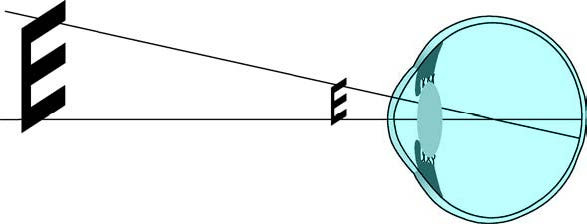
Figure 1 Visual angle
Under normal conditions, the minimum angle of resolution (MAR) perceived by the human eye when distinguishing two points is 1 arcminute (1′). On the International Standard Vision Chart, the benchmark for 1.0 visual acuity is the ability to identify optotypes that create a spatial change corresponding to this 1′ arc. Both distance and near vision charts are designed based on this standard for 1.0 visual acuity.
Expression of Visual Acuity
The formula for calculating visual acuity is V= d/D, where V is visual acuity, d is the actual observation distance for a given optotype, and D is the distance at which a normal eye should identify that optotype. Visual acuity is generally expressed in decimal form. For instance, on the International Standard Vision Chart, the optotypes for 1.0 and 0.1 lines correspond to 5m and 50m distances for detecting the 1′ arc optotype. If a person can only recognize the 1′ arc optotype at a distance of 5m rather than 50m, their visual acuity is calculated as 5m/50m=0.1.
Logarithmic Vision Charts
The standardized logarithmic vision chart features optotypes with a constant size ratio of 1.26 between adjacent rows (approximately 0.1 log units) and uses a five-point recording system. Vision charts based on the logarithm of the minimum angle of resolution (LogMAR), such as the Early Treatment Diabetic Retinopathy Study (ETDRS) chart, also use logarithmic scaling. LogMAR charts may record results in decimals or fractions, while ETDRS charts use a scoring system. Logarithmic-based vision charts are considered more suitable for research and statistical analysis.
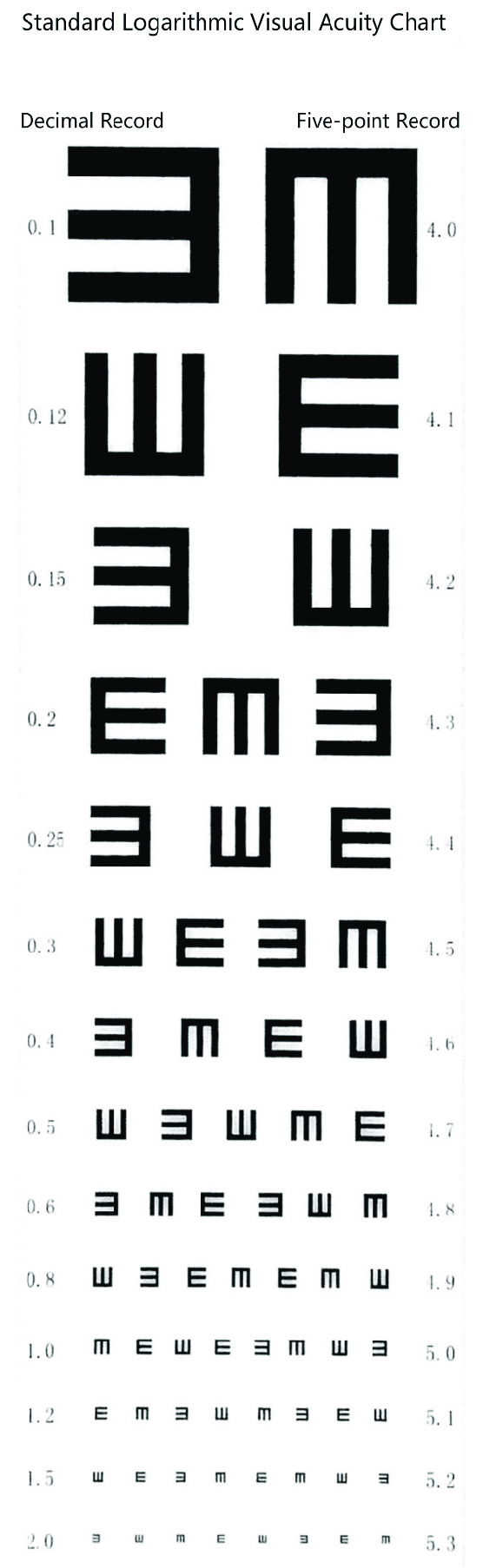
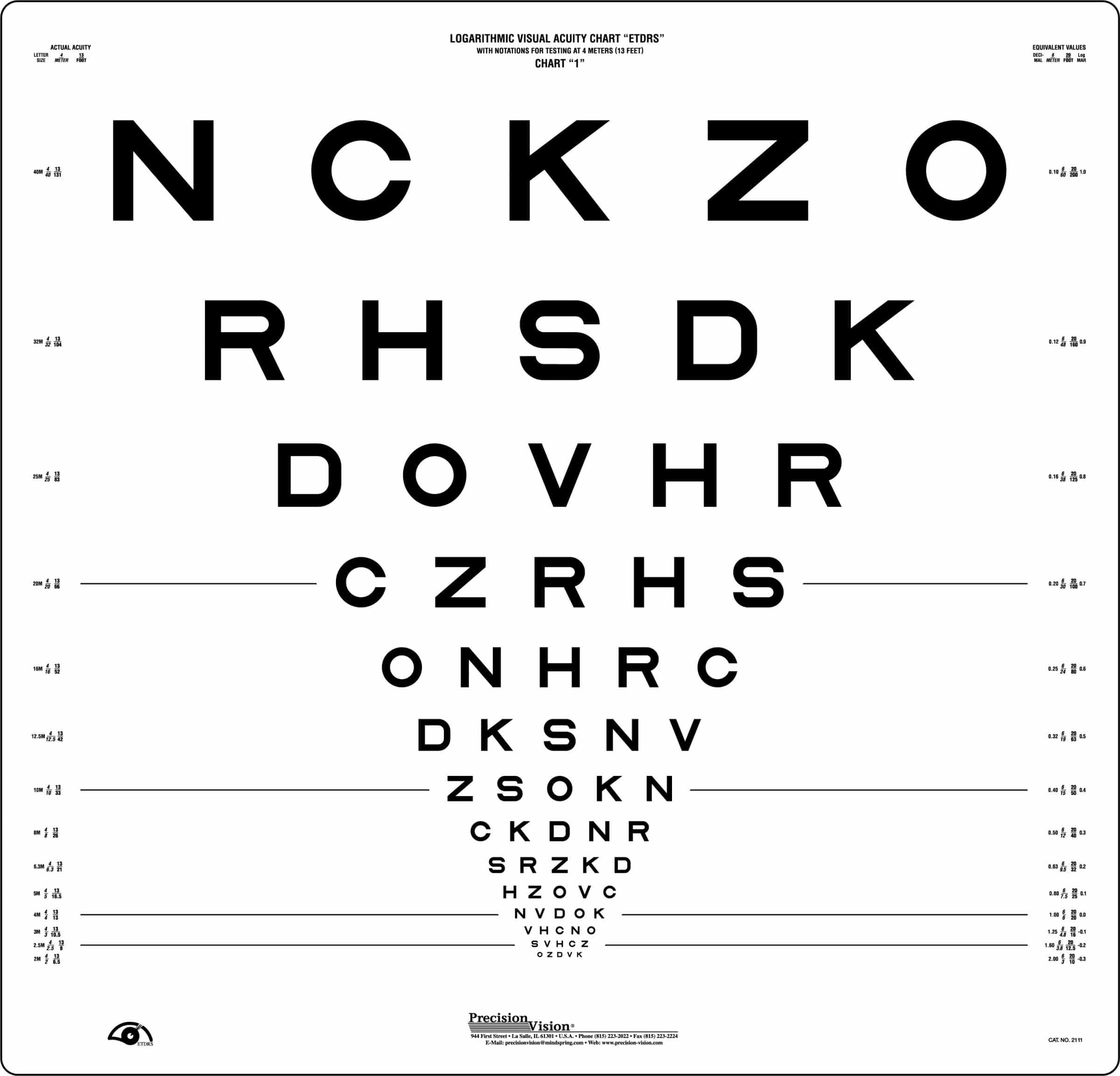
Figure 2 Standard logarithmic vision chart and ETDRS vision chart
Additionally, other charts, such as the standard logarithmic vision chart and letter-based charts like the Snellen Vision Chart, are widely used. Snellen vision testing measures "minimum reading ability" as a form of visual acuity, with the classic Snellen fraction representing the reciprocal of the MAR.
Types of Optotypes
Optotype designs vary and include "E"-shaped figures, English letters, Arabic numerals, word-based optotypes, Landolt rings with breakpoints, and simple pictogram optotypes for children.
Methods of Vision Testing
Important Considerations
Each eye is tested separately using an occluder to cover one eye, beginning with the right eye followed by the left. The occluder should not press against the eyeball. The vision chart should be illuminated with a standard light intensity of 300–500 lx. For distance visual acuity testing with the International Standard Vision Chart, the initial distance is 5m, while near visual acuity testing is performed at 30cm. The examiner uses a pointer to indicate optotypes, and the examinee is asked to identify them either verbally or with hand gestures, determining their best-recognized line.
Testing Procedures
Distance Visual Acuity Testing
Using the International Standard Vision Chart as an example, normal distance visual acuity is defined as 1.0. If the largest optotype (0.1 line) cannot be identified at a distance of 5m, the examinee progressively moves closer until they can recognize it. Visual acuity is then calculated using V=d/D. For example, if a person can only recognize the 50m optotype (0.1 line) at a distance of 3m, their actual visual acuity is V=3m/50m=0.06.
Testing with a Pinhole Plate
If the examinee's visual acuity is below 1.0, evaluation with a pinhole plate or pinhole glasses is performed. Improvement in visual acuity suggests refractive errors.
If the Largest Optotype at 1m Cannot Be Identified
Additional assessments are conducted:
Counting Fingers (CF)
The examiner holds up a varying number of fingers and asks the examinee to identify the number. The distance where this is correctly recognized is recorded, e.g., "CF at 30 cm."
Hand Motions (HM)
If fingers cannot be counted at 5cm, the examiner waves a hand in front of the examinee, and recognition of the movement is recorded, e.g., "HM at 20 cm."
Light Perception (LP)
If hand motion (HM) cannot be recognized, light perception is assessed. The examination is conducted in a dark room, with one eye tightly covered to ensure no light penetration. The examiner uses a candle or flashlight, switching it on and off from a distance of 5m. The subject is asked to identify whether light is present. If light cannot be perceived at 5m, the light source is gradually brought closer, and the farthest distance at which light is detected is recorded. If there is no perception of light, this is clinically noted as "No Light Perception" (NLP). For those with detectable light perception, additional testing for light source localization is performed (commonly referred to as light localization), which helps evaluate retinal function. The subject looks straight ahead while the examiner positions the light source 1m away from the tested eye. The light source is placed in nine positions: directly above, in the middle, and below in both the temporal and nasal quadrants (upper, midline, lower). The subject identifies the direction of the light source, recorded as "positive" ("+") or "negative" ("-") for each position, with annotations for the side of the eye and nasal/temporal direction.
Near Vision Examination
Near vision is assessed using standard near vision charts (expressed in decimal form) or the Jaeger near vision chart. Combining distance vision and near vision testing provides a general understanding of refractive conditions, such as myopia, hyperopia, presbyopia, or accommodative dysfunction. It also helps to evaluate the subject's reading ability more accurately.
Vision Testing for Children
For children under three years of age who cannot cooperate with regular vision tests, patience and observation are required. The evaluation involves checking whether fixation and following reflexes are present, providing a rough estimate of the child’s visual capability. Objective assessments, such as optokinetic nystagmus (OKN) or visual evoked potential testing, are useful for estimating visual acuity in infants and young children. For children over the age of three who cannot cooperate with standard vision tests, a pictorial vision chart may be used. In pediatric vision testing, qualitative assessment is more critical than quantitative measurement. Determining whether there is a difference in vision between the two eyes is more valuable than obtaining exact visual acuity for each eye. A difference between the vision of the two eyes may indicate the possibility of amblyopia. The level of cooperation during the vision test should also be documented as part of the assessment.
Refraction Examination
Refraction testing is primarily used to evaluate the refractive condition of the eye. It is a dynamic and multi-step clinical diagnostic process that helps determine corrective visual acuity. Cycloplegic refraction, which involves temporarily paralyzing the ciliary muscle, provides an objective degree of refractive error. Commonly used cycloplegic agents in clinical practice include 1% atropine ophthalmic ointment and 1% cyclopentolate eye drops.
A complete refraction examination consists of three stages: the initial stage, the precision stage, and the confirmation stage.
Initial Stage
In this stage, the examiner gathers basic information about the subject's refractive status. Key steps include:
- Retinoscopy or automated refraction;
- Measurement of corneal curvature using a keratometer;
- Lens power measurements using a lensometer.
- Retinoscopy is a crucial step in the initial stage.
Precision Stage
This stage involves verifying and refining the preliminary information obtained during the initial stage. The main instrument used during this stage is the phoropter. The subject responds to minor changes in lens power, making this step heavily reliant on the subject's subjective responses. Due to the subjective nature of the process, it is often referred to as subjective refraction.
Confirmation Stage
In this stage, visual acuity is fine-tuned by testing with a trial lens frame to allow for individual adjustment. For presbyopic patients, the adjustment of near addition lenses (plus lenses for reading) is included.
Static Retinoscopy
Retinoscopy is divided into two main categories: static retinoscopy and dynamic retinoscopy. Static retinoscopy is used for routine refraction and is an objective method of determining the refractive error. The results serve as the starting point for subjective refraction.
Retinoscope and Retinoscopy Principles
A retinoscope uses an illumination system to direct light into the eye and illuminate the retina. The light reflected back from the retina passes through the refractive components of the eye, undergoing changes that provide insight into the refractive condition. Based on the shape of the projected light spot, there are two types of retinoscopes: spot retinoscopes and streak retinoscopes. Currently, clinical practice predominantly uses streak retinoscopes.
Figure 3 Diagram of a retinoscope and the principles of retinoscopy
1, Plane mirror and central aperture
2, Condensing lens
3, Streak sleeve
4, Technique for holding the retinoscope
5, Movable slider (moves up and down)
As the retinoscope's streak of light moves, the movement of the reflected light on the retina becomes visible. The qualities of the streak of light and its movement help determine the refractive status of the eye. Different refractive types produce different reflected light characteristics:
- Emmetropia produces parallel light rays;
- Hyperopia produces divergent light rays;
- Myopia produces convergent light rays.
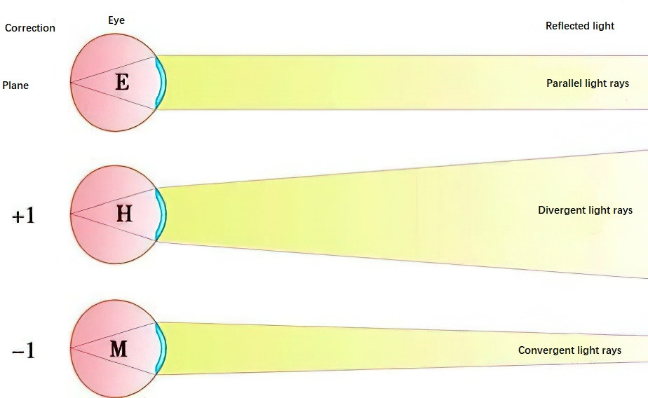
Figure 4 Differences in reflected light based on refractive status
Retinoscopy involves first identifying whether the reflex movement is "with" or "against" the light streak. Next, brightness, speed, and width of the reflex are assessed to estimate the distance from the neutral point. When the retinoscope’s position is conjugate to the retinal plane, the reflex fills the pupil and no longer moves with the light streak.
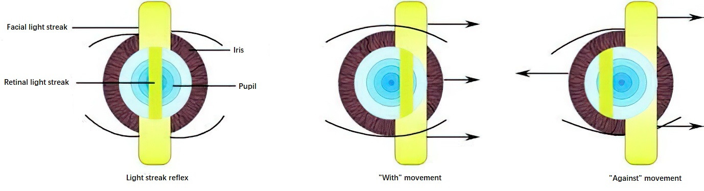
Figure 5 Reflex motions: "With" movement and "Against" movement
Typical working distances in clinical practice are 67cm or 50cm. For example, if the neutral point is reached at 50cm, corresponding to a +3.00D lens power, the subject's refractive error is calculated as (+3.00D) – (+2.00D) = +1.00D.
Principles of Retinoscopy
The refractive status of the eye, whether spherical or astigmatic, can be determined by adjusting the sleeve position of the retinoscope, altering the examination distance, and rotating the light streak of the retinoscope to observe phenomena such as break, thickness, and deviation. If the refractive error is spherical, the reflex motion observed will either move "with" or "against" the movement of the light streak. Positive lenses or negative lenses are added incrementally until no motion within the pupil is observed (neutralization is achieved).
For astigmatism, it is first necessary to determine the directions of the two principal meridians and then neutralize the refractive errors within each meridian separately. When using the negative cylinder lens in a phoropter, one meridian is corrected solely with a spherical lens, while the other is corrected with a negative cylinder lens. After neutralizing both principal meridians, the neutralized meridians are reviewed using a spherical lens for confirmation, with adjustments made to the spherical lens power as necessary. The power obtained from retinoscopy requires subtraction of the dioptric power corresponding to the working distance, yielding the final retinoscopic refractive power.
Subjective Refraction
The determination of refractive status using a subjective method is referred to as subjective refraction. This requires standard equipment, including a phoropter and a projection vision chart.
Phoropter
The phoropter, also known as a refractor, is equipped with a set of high-power spherical lenses on the inner rotary dial, lower-power spherical lenses on the central dial, and cylindrical lenses on the outermost dial. In addition to spherical and cylindrical lenses, the phoropter's control wheel includes various auxiliary lenses, such as occlusion lenses, Maddox rods, retinoscopy working-distance lenses (+1.50D or +2.00D), pinhole disks, polarizing filters, and prism lenses. As a result, the phoropter is not only used for refraction testing but is also applicable for evaluating visual function, including abnormalities of accommodation and convergence.
Subjective Refraction Procedures
Monocular Distance Subjective Refraction
Monocular subjective refraction occurs in three stages:
- Initial MPMVA (Maximum Plus to Maximum Visual Acuity): Identifying the initial effective spherical correction;
- Refining Cylinder Power and Axis: Using the cross cylinder to refine the cylinder axis and power (initial values are typically obtained from keratometry or retinoscopy);
- Finalizing Spherical Power: Performing the final refinement of spherical correction, also referred to as the "final MPMVA."
Initial MPMVA
The main goal of monocular MPMVA is to control accommodation in the tested eye. This is typically achieved by inducing “fogging,” which involves adding excessive positive sphere power (+0.75D to +1.00D) to relax accommodation. Fogging reduces vision intentionally, allowing accommodation to relax. Excessive fogging may impair the system's ability to detect small variations caused by accommodative changes.
Refining Astigmatism with the Cross Cylinder
The refinement of cylinder axis and power involves the use of Jackson Cross Cylinder (JCC), a tool with equal power but opposite signs across its two perpendicular principal meridians (±0.25D). The principal meridians are indicated by colored dots: red for the negative cylinder axis and white for the positive cylinder axis. The JCC can be applied to refine both the cylinder axis and the cylinder power.
Finalizing MPMVA
The steps and endpoint for the final MPMVA are similar to those of the initial MPMVA. If no changes in cylinder axis or power were identified during the cross-cylinder process, or if no astigmatism was found initially, this step may be unnecessary.
Binocular Distance Subjective Refraction
Binocular refraction involves balancing accommodation and performing MPMVA binocularly.
Binocular Accommodation Balance
This step ensures that both eyes are in balance only when their corrected visual acuity (after monocular refraction) is approximately equal and does not differ by more than one line. The steps include:
- Removing any occlusion from either eye and inducing binocular fogging with a standard sphere power of +0.75D (or greater if needed) to reduce acuity to 0.5–0.8;
- Using vertical prisms to dissociate the images viewed by both eyes to disrupt fusion. A Risley prism in the phoropter is typically adjusted to place 3–4Δ Base-Up (BU) in front of the right eye and 3–4Δ Base-Down (BD) in front of the left eye, allowing the patient to perceive two separate images, one above the other. The best visual acuity line prior to fogging is used.
- The patient is asked to compare the clarity of the upper and lower rows. If the upper row is clearer, +0.25D is added to the left eye (the eye perceiving the upper image). This process is repeated until both images appear equally blurry. The endpoint is reached when both images are perceived with equal clarity, indicating zero accommodation and balanced fogging. If equal clarity cannot be achieved, the dominant eye should retain a slightly clearer image.
Two conditions must be met throughout binocular balancing:
- Both eyes must continuously see the target;
- Both eyes must remain fogged during the process.
Binocular MPMVA
The process is essentially the same as for monocular MPMVA.